Glossary of RF & Microwave Terms
A B C D E F G H I J K L M N O P Q T U V W X Y Z
A - G |
Attenuation |
| Loss of signal in transmission through a filter, usually referring to signal amplitude or signal power. Usually measured in decibels (dB). |
Ball Bond |
| The thermo-compressed bond between a metalized pad and a wire which has a ball shaped end to it. |
Band Reject Filter |
| A filter that rejects one band of frequencies and passes both higher and lower frequencies. Sometimes called a notch filter. |
Bandpass Filter |
| A filter that passes one band of frequencies and rejects both higher and lower frequencies. |
Bandwidth |
| The width of the pass band of a bandpass filter is usually expressed as the frequency difference between lower and upper relative 3dB points. |
Center Frequency (Fc) |
| The arithmetic mean frequency is normally calculated using the 3dB relative band edges (F1 & F2). Fc = ( Fl + F2 ) / 2 Where F1 and F2 are lower and upper frequencies respectively at which a particular signal attenuation occurs, usually taken as 3dB relative attenuation - an important parameter of bandpass and bandstop filters. |
Conversion Loss |
| The ratio in dB of the IF output of a mixer to the rf input power. All conversion loss measurements and specification are normally based on the mixer being terminated on all ports and a stated LO signal power level being applied. |
Cutoff Frequency (Fco) |
| The upper passband edge in lowpass filters or the lower passband edge in highpass filters. The passband edge closest to the stop band. Normally the point at which the VSWR equals 1.5:1. |
Dynamic Range |
| The range, from the minimum, which is at a level 3 dB above the amplifier's internally generated floor, to a maximum input signal level that a component can accept and amplify without distortion. Dynamic Range = P1dB - PMDS Where: PMDS = Minimum detectable signal 3 dB above the noise floor. |
Elliptic Function |
| A mathematical function used to yield the squarest possible amplitude filter response with a given number of circuit elements, The elliptic function has a CHEBYSHEV response in both the passband and the stopband. The elliptic function filter has a poorer phase response and transient response than any of the classical transfer functions. |
Envelope Delay |
| The propagation time delay of the envelope of an amplitude modulated signal as it passes through a filter. Sometimes called time delay or group delay. Envelope delay is proportional to the slope of the phase shift response versus frequency curve, Envelope delay distortion occurs when the delay is not constant at all frequencies in the passband area. |
Eutectic Bonding |
| The term for properties of an alloy that have the lowest melting point. In eutectic bonding, the ingredients involved go from completely molten to solid without going through a slushy phase at the eutectic composition. Eutectic bonding also provides superior heat transfer for active devices. |
Gain |
| Gain is the ratio of the power output to the power input of the amplifier in dB. The gain is specified in the linear operating range of the amplifier where a 1 dB increase in input power gives rise to a 1 dB increase in output power. Gain = 20*log(S21) |
Group Delay Deviation |
| Generally specified as the deviation between two points within the passband (i.e., 10 NS P-P). Excessive delay deviation results in modulated signal distortion. |
H - N |
Highpass Filter |
| A filter which passes high frequencies and rejects low frequencies. |
Insertion Loss |
|
Insertion Loss (dB) is defined as the drop in power as a signal enters an RF component. This value not only includes the reflected incoming signal, but also the attenuation of the component.
Insertion Loss (dB) = 10 * LOG10(Output Power/Incident Power)
The loss of signal caused by a filter being inserted in a circuit. In general, it is the ratio of voltage delivered to the load (at peak frequency response) with the filter in the circuit, to the voltage in the load if a perfect lossless matching transformer replaced the filter.
|
Isolation |
| The ratio (expressed in dB) of the power level at one port compared to the resulting power level of the output port. |
Limiting Level |
| This is the input power level when the output power is goes into compression and no longer becomes linear. |
Linear Phase Filter |
| A filter that exhibits a constant change in degrees per unit of frequency. The resultant plot of frequency versus phase is a straight line. This type of filter ideally displays a constant delay in its passband. |
Lowpass Filter |
| A filter which passes low frequencies and rejects high frequencies. |
Noise Figure / Noise Factor |
|
The Noise Factor of a transducer at a specified input frequency is the ratio of (a/b) where “a and b” are:
(a) the available Signal to Noise Ratio (SNR) at the signal generator terminals per unit bandwidth when the temperature of the input termination (generator or source) is 290°K and the bandwidth is limited by the transducer, to
(b) the available SNR per unit bandwidth at the output terminals of the transducer.
Traditionally:
Noise Figure NF = 10 log(noise factor F) Noise Temperature (Te) = To(F - 1) Where: Te is the noise temperature To is standard temperature 290 K F is noise factor For example, a noise figure of 2.0 dB is equivalent to a Noise Temperature of 170 K
|
Noise Floor |
| This is defined as the lowest possible input to a chain or a component, that will produce a detectable output. |
Noise Temperature |
| This is the amount of thermal noise in a chain or a component. Noise Factor and Noise Temperature (Te) are related as follows: Noise Temperature (Te) = (F - 1)To Where: Te is the noise temperature To is standard temperature 290 K F is noise factor For example, a noise figure of 2.0 dB is equivalent to a Noise Temperature of 170 K. |
O - P |
One dB Compression Point |
|
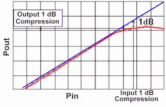
The 1 dB compression point is the point on a Pout vs. Pin graph, where an increase power input causes the measured gain to decrease from the linear gain by one dB. Typically, if not explicitly stated, the 1 dB compression point refers to the output power (Pout) at that point.
|
Overshoot |
| The amount in percent by which a signal exceeds its steady-state output on its initial rise. |
Passband |
| The frequency range in which a filter is intended to pass signals. |
Passband Ripple |
| Variations of attenuation with frequency within the passband of a filter. |
Phase Shift |
| The changing of phase of a signal as it passes through a filter. A delay in time of the signal is referred to as phase lag and in normal networks, phase lag increases with frequency, producing a positive envelope delay. |
PIN Diode |
| A diode where a thin layer exists between the N and P regions. Rectification with pin diodes is limited. They actually behave more like a variable resistor that changes based upon the DC bias. |
Pulling |
| The difference between the maximum frequency of a VCO when the phase angle of the load impedance reflection coefficient varies through 360 degrees. |
Pushing |
| The change in frequency when the supply voltage changes, expressed in MHz/V. |
Q - T |
Relative Attenuation |
| Attenuation measured with the point of minimum attenuation taken as zero dB. |
Return Loss |
|
1. Return Loss (dB) is defined as a ratio of the incoming signal to the same reflected signal as it enters a component.
Return Loss (dB) = 10 * LOG10(Reflected Power/Incident Power) 2. The ratio in dB of maximum power sent down a transmission line to the power returned toward the source, Also equal to 20 times the log of the reciprocal of the reflection coefficient.
|
Ringing |
| The tendency of a filter to oscillate for a time when a transient waveform is applied to it. |
Ripple |
| Generally referring to the wavelike variations in the amplitude response of a filter. Chebyshev and elliptic function filters ideally have equi-ripple characteristics, which means that the difference in peaks and valleys of the amplitude response in the passband are always the same. Butterworth, Gaussian, and Bessel functions have no ripple. Ripple is usually measured in dB. |
Scattering Parameters |
|
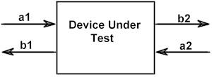
Better known as S-Parameters, these 4 values help define the performance of several variables at various frequencies.
S11 (Input Reflection Coefficient ) = b1/a1 S12 (Isolation) = b1/a2 S21 (Forward Transfer Coefficient or Gain /Loss) = b2/a1 S22 (Output Reflection Coefficient) = b2/a2
|
Shape Factor |
| An important parameter of all filters: 1. BANDPASS:SF = Attenuation Bandwidth/3dB Bandwidth 2. BANDSTOP:SF = 3dB Bandwidth/Attenuation Bandwidth 3. LOWPASS:SF = Attenuation Frequency/Fco 4. HIGHPASS:SF = Fco/Attenuation Frequency |
Spurious Free Dynamic Range |
| Spurious Free Dynamic Range = 2/3 (PTOI - Gain - PMDS) Where: P1dB = 1 dB Output Compression Point PTOI = Third Order Intercept PMDS = Minimum detectable signal 3 dB above the noise floor. |
Stopband |
| The area of frequency where it is desirable to reject or attenuate all signals as much as practical. |
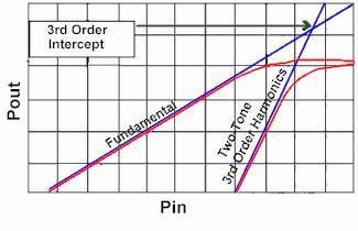
Third Order InterceptThe third order intercept is the intercept point formed by the intersection of the fundamental output and the two-tone third order distortion product, when plotted as a theoretical linear function of input power. The higher the Third Order Intercept, the lower the intermods for the incoming signals.

|
Time Delay |
| The amount of time it takes for certain signals to pass through a filter. |
U - Z |
Voltage Standing Wave Ratio |
| The ratio between the peak and valley of standing waves on a transmission line. |
VSWR |
| Voltage Standing Wave Ratio simply put is the ratio of the maximum to the minimum voltage of a standing wave (which is the instantaneous sum of incident and reflected waves). Ideal is a figure of 1:1 which means that 100% of the incoming signal passed through the component without any reflection. In that case, there would be no standing wave. A 2:1 VSWR (or mismatch) means that 12% of the incoming signal was reflected. |
Wedge Bond |
| It is the bond that exists between the substrate and the wire. The term wedge comes from the tool used to perform this operation which is wedge shaped. |

